A bill of materials (also known as a BOM or bill of material) is a comprehensive list of parts, items, assemblies and other materials required to create a product, as well as instructions required for gathering and using the required materials. The bill of materials can be understood as the recipe and shopping list for creating a final product. The bill of materials explains what, how, and where to buy required materials, and includes instructions for how to assemble the product from the various parts ordered. All manufacturers building products, regardless of their industry, get started by creating a bill of materials (BOM).
Because the bill of materials pulls together all sorts of product information, it is common that several disciplines (design and engineering, document control, operations, manufacturing, purchasing, contract manufacturers and more) will consume data contained within the BOM record to get the job done right. In fact, engineers and manufactures rely so heavily on BOMs they their own special subsets called the engineering bill or materials (EBOM) and the manufacturing bill of materials (MBOM). The BOM guides positive results from business activities like parts sourcing, outsourcing and manufacturing, so it is important to create a BOM that is well organized, correct and up to date.
And for companies that outsource manufacturing activities, it is especially important to create an accurate and revision-controlled bill of materials. Any time the BOM is handed off to a contract manufacturer (CM) or supplier, it should be correct and complete, otherwise you can expect production delays.
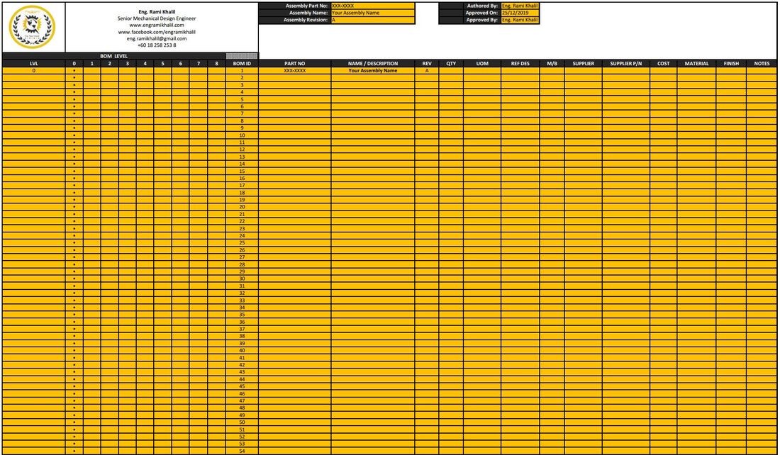
Because one of the main functions of the BOM is to ensure that the product is built right, it is best to include specific pieces of product data in the BOM record. Hereinafter, I share with a BOM document includes the following information:
Creating a bill of materials is not only a necessary step in the product development process, it is also what makes your product design a reality. Before you create a BOM record, it is important to consider who will utilize the information and how you will maintain and manage all associated product documentation like part datasheets and CAD files. Develop more efficient manufacturing practices by capturing detailed part information when creating a bill of materials.
Because the bill of materials pulls together all sorts of product information, it is common that several disciplines (design and engineering, document control, operations, manufacturing, purchasing, contract manufacturers and more) will consume data contained within the BOM record to get the job done right. In fact, engineers and manufactures rely so heavily on BOMs they their own special subsets called the engineering bill or materials (EBOM) and the manufacturing bill of materials (MBOM). The BOM guides positive results from business activities like parts sourcing, outsourcing and manufacturing, so it is important to create a BOM that is well organized, correct and up to date.
And for companies that outsource manufacturing activities, it is especially important to create an accurate and revision-controlled bill of materials. Any time the BOM is handed off to a contract manufacturer (CM) or supplier, it should be correct and complete, otherwise you can expect production delays.
Because one of the main functions of the BOM is to ensure that the product is built right, it is best to include specific pieces of product data in the BOM record. Hereinafter, I share with a BOM document includes the following information:
- Level (LVL): A single digit which indicates on what level of the BOM the part resides.
- BOM ID: This number uniquely identifies a particular line within your BOM.
- Part No.: The part or assembly identification number.
- Description: Name or short description of the particular part or assembly.
- Revision (REV): The revision level of the particular part or assembly. Typically, only used for parts you design.
- Quantity (QTY): The numerical quantity required of a part or assembly, or, depending on the unit of measure, the precise amount of a material required.
- Unit of Measure (UOM): Typically, this is EACH for individual parts or assemblies, but for certain items (e.g. tape, grease, insulation, etc.) a specific unit is used instead.
- Supplier: The specific vendor who will supply the part, if purchased.
- Supplier Part No.: The specific vendor's own internal part number if it differs from what is shown in PART NO.
- Material: Raw material specification for newly manufactured parts.
- Finish: Field to specify any material finishes, heat treatments, or other processes to be applied to the part.
Creating a bill of materials is not only a necessary step in the product development process, it is also what makes your product design a reality. Before you create a BOM record, it is important to consider who will utilize the information and how you will maintain and manage all associated product documentation like part datasheets and CAD files. Develop more efficient manufacturing practices by capturing detailed part information when creating a bill of materials.


 RSS Feed