Industrial Parallel Robot:
Industrial Parallel Robot:
CAD software used: Autodesk Inventor 2018.
Download Scope: 3D CAD model (Autodesk Inventor files), STEP. Price: 15$
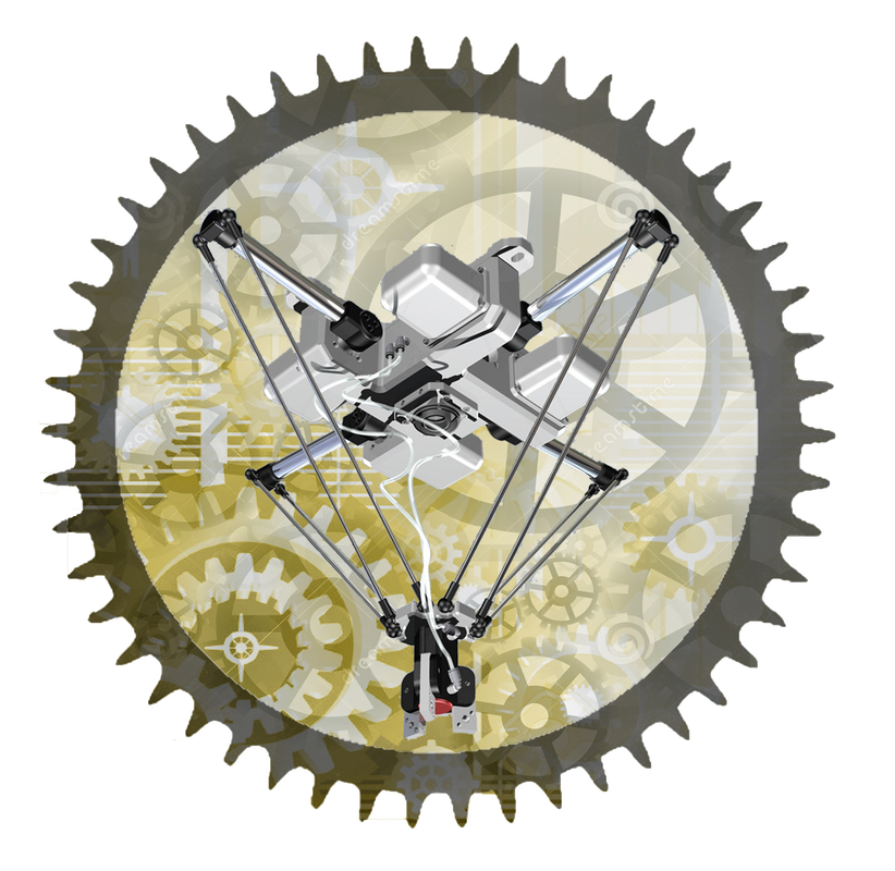
An industrial parallel robot, "ARMO", has (5) degrees of freedom (DOF). Parallel robots differ from series robots mainly in one point: in parallel robots, all arms are connected directly to the actuator head, while in series robots, the robot consists of a single arm made up of many sequential joints starting from the robot base and ending with the actuator head with one joint directly connected. This robot seems to be simple in terms of mechanical design, and the equipment needed to build it is also simple. However, the difficulty remains in the kinematic and dynamic analyses. The actuator head of this robot can move towards the three axes (X, Y, Z) with limited ability to rotate around the (X, Y) axes. Therefore, the robot has (5 DOF) according to the six points theory.
According to the kinematic analysis, I depended on the arms linked to each other by two bases for the purpose of reaching the target point. The first base is fixed and represents the robot body, while the second base can move and represents the actuator head base. The number of arms is (4), where each two arms are located in one plane. The two resulting planes are perpendicular to each other since the angle between two adjacent arms is (90 degrees). In fact, each arm is divided into two successive joints to give more flexibility in motion to the robot. The two joints have a total of (5 DOF), and they are all rotational. By putting the arms to result in a (90 degrees) angle between each adjacent arm and connecting the arms to the actuator head base, we get an actuator head with (5 DOF); three are linear and two are rotational. By putting some limiting conditions regarding the design and dimensions issues, I was able to reach the full kinematic diagram, which represents the work space of the robot. With this diagram, we can determine the value of each arm rotation according to the purpose point parameters. As a result, I was able to reach (4) kinematic equations to determine the purpose point movement. Each two arms in the same plane have two equations linked to each other, and these equations are linked to the two equations resulted from the other plane. According to the dynamic analysis, I studied the inertia forces and torques, as well as the velocity required to move the actuator head. Consequently, stepper motors were chosen, with a number equal to the number of leader joints formed by the four arm joints. These motors rotate (1.8 degrees) by each pulse they receive and are characterized by good accuracy. The value of rotation is considered to determine the robot's accuracy. The load torque for each motor is (4.4 Kg.cm). Regarding the design aspect, the four arms have (5 DOF) each: rotational for the first joint, rotational for the second joint around the first joint axis, and an additional (3 DOF) earned by using Ball and Sockets Joints. The ball and socket joints play an important and effective role in giving flexibility in robot motion. For the purpose of the four leader joints calibration, four micro switches are used with a suitable mechanism for them. As for the actuator head, it is a gripper with three jaws. The gripper works pneumatically using compressed air and is directed using a 4/2 single solenoid valve. The robot is provided with a vision system for monitoring targets by installing an industrial camera that can capture mono-color or full-colored photos with a resolution of (656×490 pixels). With regard to the Robot Work Space, I created the full kinematic diagram by studying all possible ways in which the four leader joints can rotate. To reduce the time needed to complete the work space purpose, I increased the value that each stepper motor can rotate by each pulse by a factor of five. As a result, I obtained a diagram that shows all possible positions for the actuator head location (the green lines). Since the limiting values for each stepper motor rotation are 55 degrees upward and 75 degrees downward, the number of these positions is 523. By connecting the centers of the limiting green lines, we can determine the work space, which is represented by the closed red curve. This red curve is similar to armor, and I named this robot "ARMO" accordingly. It is important to note that this diagram expresses the motion for two arms in the same plane. Therefore, there is another diagram that is perpendicular to this one for the other two arms. Consequently, the robot work space changes from an "armor" plan to a vacuity one. We can obtain the dimensions of this space, which is located under the robot body at a specific distance, from the work space. The actuator head can move in the vertical direction by a maximum of 35 cm and can draw a circle with a maximum diameter of 55 cm, depending on the actuator head location. |
|
|
|