Industrial Robotic Arm:
Industrial Robotic Arm:CAD software used: Autodesk Inventor 2018.
Download Scope: 3D CAD model (Autodesk Inventor files), STEP. Price: 15$
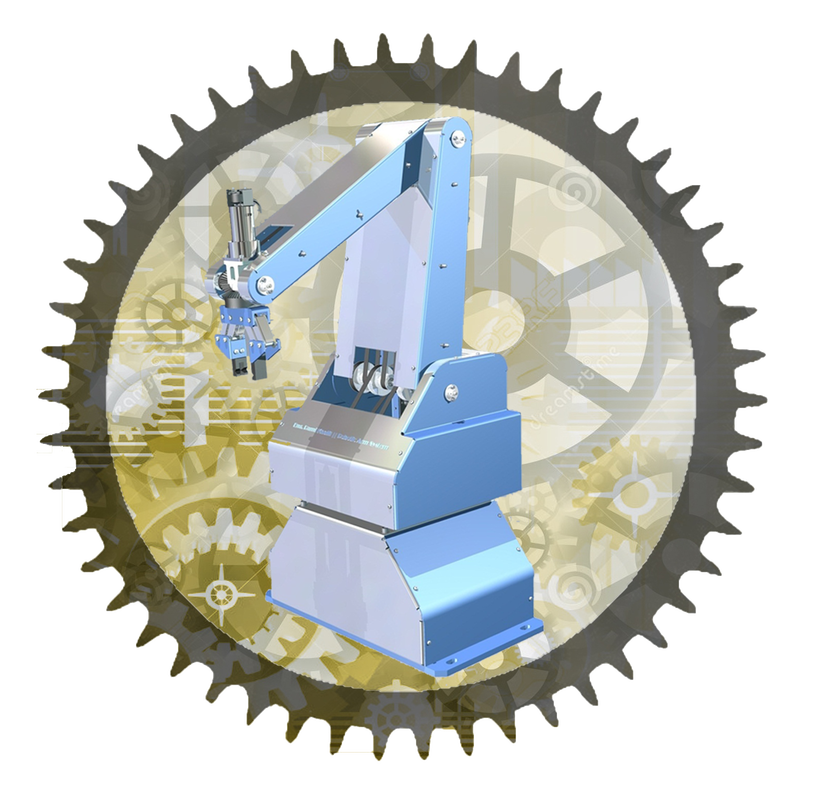
An industrial robotic arm with 5 axes is designed to excel mechanically using synchronous pulleys and belts to generate its movements. Additionally, it uses electrical motors that work using direct current. The motors have a low number of rpm (rounds per minute), and the direction of rotation can be controlled by means of the reverse of feeding polarity. The motors are provided with encoders that have a high level of accuracy, and they can give 1024 pulses for each rotation of the motor axis, i.e., one pulse for each 0.35 degrees of rotation.
The robot consists of a rotary base, which represents the first axis of the robot, and it can rotate with 360 degrees. The arm, which is connected to the base, represents the second axis of the robot, and it can rotate with only 80 degrees. The arm connected to the previous arm represents the third axis of the robot and can rotate with 120 degrees. Regarding the actuator end of the robot, which is represented by a mechanical gripper, it represents both the fourth and fifth axes. It can rotate around two perpendicular axes, giving the robot two degrees of freedom in addition to the three degrees of freedom resulting from the previous axes. Therefore, the robot has five degrees of freedom (DOF). The robot has six direct current motors, one motor for each axis. The sixth motor is used to generate the movement for the gripper's two jaws according to the "open" and "close" cases. The gripper mechanism consists of one pair of worm gears driven by one worm, so the worm rotation results in the rotation of the two worm gears in opposite directions. The greatest angle that the gripper can open is 60 degrees. The rotation of the actuator end around two perpendicular axes can be achieved using three bevel gears. Two of them are assembled on one axis in the opposite direction, and the third bevel gear is assembled to the other axis. The movement method can be explained as follows: when the two opposite bevel gears turn in opposite directions, the third bevel gear turns around its axis, and the gripper turns around its axis. On the other hand, when the two opposite bevel gears turn in the same direction around their axis, the third bevel gear doesn't turn around its axis and turns around the other two gears, and the gripper turns around the axis of two opposite bevel gears. The space of work diagram for this robot is illustrated in one of the above pictures. |
|
|
|