Rapid Prototyping - 3D Printer Machine:
Rapid Prototyping - 3D Printer Machine:CAD software used: Autodesk Inventor 2018.
Download Scope: 3D CAD model (Autodesk Inventor files), STEP. Price: 20$
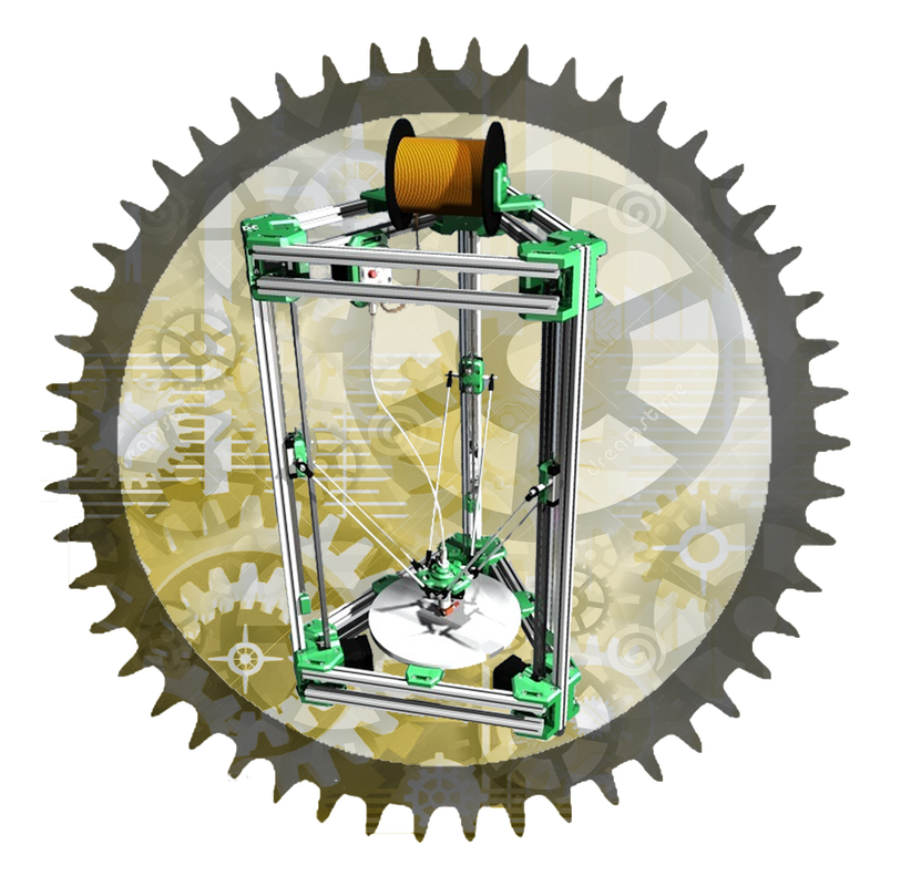
A small size 3D printer, a type of rapid prototyping machine (RP), has a circular work area with a diameter of 20 cm and a maximum height of 160 mm along the Z-axis. Based on kinematic analysis, the three Cartesian axes (X, Y, Z) are transformed into three parallel axes using the polar representation method. In this method, the (X, Y, Z) coordinates are replaced by two coordinates: the radius starting from the center of the work table and the angle starting from zero degrees according to the original circle. The angle is zero starting from the left and increases counterclockwise. The machine uses a mechanism similar to that used in parallel robots, which is represented by six joints in the pictures. In reality, every two adjacent joints are considered one joint. This is done to prevent rotation around any of the three axes, known as the Six Point theory, allowing the actuator head to remain with three degrees of freedom (DOF), which are the motion toward the direction of (X, Y, Z) axes. Using this mechanism and polar representation, the three Cartesian axes are transformed into three parallel axes located at the three angles of an equilateral triangle.
To draw a specific slide at the height of zero, i.e., when the actuator head is in contact with the work table, every point included in the cross-section of the slide needs to be determined and represented using the polar representation. The movement of the sliding blocks related to joints located on each axis allows reaching every point. Kinematic equations should be determined to find the point that needs to be reached at a certain height, and the number of these equations equals the number of the axes. At the point where the radius and the angle for the polar representation are specified, a vector projection is performed for all three joints on the work area with a radius of 20 cm. Considering that the actuator head can be represented as a point, the projection of joints will intersect at one point, which is the actuator head located at the specified point. Using Sin's theory and Pythagoras theory, along with some additional factors resulting from the design dimensions and deviations, the three kinematic equations expressing the distances that each sliding block should move to reach the specified point at the specified height can be obtained. Dynamic analysis studied the inertia forces and torques, allowing determining the maximum and minimum velocity required to move the actuator head. Consequently, stepper motors were chosen, and the number of them is equal to the number of the axes. These motors rotate 0.9 degrees by each pulse they receive and are characterized by high accuracy. The value of rotation is taken into consideration to determine the printer's accuracy. The load torque for each motor is 3.6 Kg.cm. For the purpose of moving the sliding blocks, a motion method depending on synchronous pulleys and belts was used. This method is characterized by very high accuracy. Additionally, linear guide ways were used. Microphoto sensors, three in number, were used for calibration. The actuator head was provided with a protection system against vertical shocks with the work table or the slide created on the table below the actuator head. This system uses a pressure spring, microphoto sensor, and guides. Regarding the printing material, it is a kind of thermoplastic that is melted at a specific temperature. Usually, in a 3D printer, two kinds of thermoplastic are used: ABS and PLA. PLA (Polylactic Acid) is softer than the other kind and has a melting temperature between 190-200 degrees Celsius. This plastic can be melted using a ceramic heater located below the actuator head in the copper body, which results in melted plastic flowing from the head nozzle. The nozzle has a 0.5mm hole. This kind of thermoplastic is found like a thread coiled around a roller. The diameter of this thread is either 1.75 or 3mm, and the used diameter is the first one. The cooler made from aluminum is used to prevent the heat which comes from the ceramic heater to reach the upper points. The heat discharging can be done using a fan. Feeding with the plastic thread is done using a special mechanism that pulls the thread by means of a bearing and a roller to force the thread to go into the hose connected to the actuator. |
|
|
|