ENG. RAMI KHALIL
  • Main Page
  • Vision
  • About Eng. Rami Khalil
  • Services
  • Projects
  • Art of Engineering
  • Publications
  • Courses
  • Library
  • Programs
  • Documents
  • Articles
  • Topics Archive
  • Lectures
  • Contributions
  • Contact Us

Additive Manufacturing - Inkjet Printing Technology:

22/8/2015

0 Comments

 
The additive fabrication technique of inkjet printing is based on the 2D printer technique of using a jet to deposit tiny drops of ink onto paper. In the additive process, the ink is replaced with thermoplastic and wax materials, which are held in a melted state. When printed, liquid drops of these materials instantly cool and solidify to form a layer of the part. For this reason, the process if often referred to as thermal phase change inkjet printing. Inkjet printing offers the advantages of excellent accuracy and surface finishes. However, the limitations include slow build speeds, few material options, and fragile parts. As a result, the most common application of inkjet printing is prototypes used for form and fit testing. Other applications include jewelry, medical devices, and high-precisions products. Several manufactures have developed different inkjet printing devices that use the basic technique described above. Inkjet printers from Solidscape Inc., such as the ModelMaker (MM), use a single jet for the build material and another jet for support material.
The inkjet printing process, as implemented by Solidscape Inc., begins with the build material (thermoplastic) and support material (wax) being held in a melted state inside two heated reservoirs. These materials are each fed to an inkjet print head which moves in the X-Y plane and shoots tiny droplets to the required locations to form one layer of the part. Both the build material and support material instantly cool and solidify. After a layer has been completed, a milling head moves across the layer to smooth the surface. The particles resulting from this cutting operation are vacuumed away by the particle collector. The elevator then lowers the build platform and part so that the next layer can be built. After this process is repeated for each layer and the part is complete, the part can be removed and the wax support material can be melted away.

Explaining Video for the process:

Facebook:

تقنيات التصنيع بالإضافة -|8|- التصنيع بالإضافة - تقنية الطباعة بالحبر المبثوق (Inkjet...

Posted by Eng. Rami Khalil on Saturday, August 22, 2015
0 Comments

Additive Manufacturing - Laminated Object Manufacturing (LOM) Technology:

18/8/2015

0 Comments

 
LOM was developed by Helisys of Torrance, CA in 1991. The main components of the system are a feed mechanism that advances a sheet over a build platform, a heated roller to apply pressure to bond the sheet to the layer below, and a laser to cut the outline of the part in each sheet layer. Parts are produced by stacking, bonding, and cutting layers of adhesive-coated sheet material on top of the previous one. A laser cuts the outline of the part into each layer. After each cut is completed, the platform lowers by a depth equal to the sheet thickness (typically 0.05-0.5 mm), and another sheet is advanced on top of the previously deposited layers. The platform then rises slightly and the heated roller applies pressure to bond the new layer. The laser cuts the outline and the process is repeated until the part is completed. After a layer is cut, the extra material remains in place to support the part during build.

Explaining Video for the process:

Facebook:

تقنيات التصنيع بالإضافة -|7|- التصنيع بالإضافة - تقنية التصنيع الصفائحي للجسم (Laminated Object Manufacturing -...

Posted by Eng. Rami Khalil on Tuesday, August 18, 2015
0 Comments

ISO DIN 2768 Standard:

1/8/2015

1 Comment

 
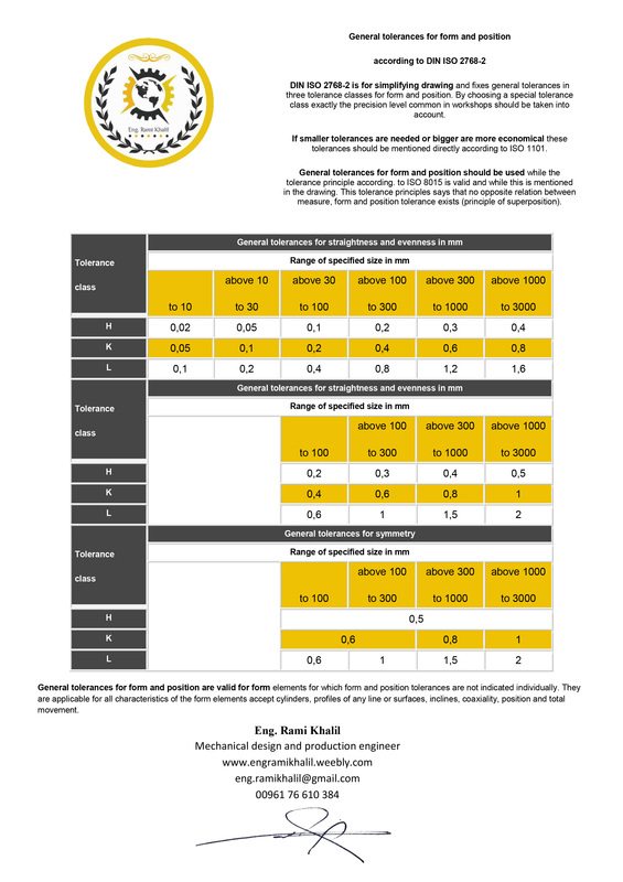
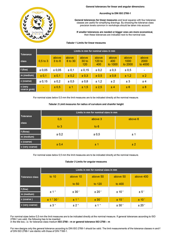
The standard ISO DIN 2768 is a standard has been issued by the International Organization for standardization - ISO in association with Deutsches Institut für Normung - DIN. This standard determines the general tolerance values for the untoleranced linear and angular dimensions and also for the form and position tolerances. It's used to simplify the engineering drawings in case of determining the mechanical tolerances for parts' dimensions which are manufactured by machining means.
This standard consists of two sub-standards:
1- ISO DIN 2768-1 Standard:
This sub-standard determines the values of general tolerances of the linear and angular dimensions and radius of curvature and chamfer height according to four classes of levels: f (fine), m (medium), c (coarse), v (very coarse).
2- ISO DIN 2768-2 Standard:
This sub-standard the values of general tolerances in regard of form and posistion according to three classes or levels: H (fine), K (medium), L (coarse).
In engineering drawings, and for the untoleranced dimensions, the medium level is usually used ( "m" for the first sub-standard and "k" for the second sub-standard), and that can be expressed by writing the following in the title box: ISO DIN 2768 - mK.

Facebook:

المعيار ISO DIN 2768:---------------------------المعيار ISO DIN 2768 هو معيار دولي صادر عن المنظمة الدولية للمعاير...

Posted by Eng. Rami Khalil on Friday, July 31, 2015
Picture
Picture
Download File
1 Comment
    Picture

    Eng. Rami Khalil

    Mechanical Design and Production Engineer.

    Archives

    September 2019
    November 2018
    October 2018
    August 2018
    December 2017
    February 2016
    January 2016
    December 2015
    November 2015
    October 2015
    September 2015
    August 2015
    June 2015
    May 2015
    April 2015

    Categories

    All
    Additive Manufacturing Standardization
    Additive Manufacturing Technologies
    Automation Technologies
    Machine Design
    Manufacturing Technologies
    Mechanics Of Materials
    Metrology

    Facebook:

    Youtube:

    RSS Feed

Services

  • CNC Machine Design
  • Robotic System Design
  • Mechanical Design Services

Eng. Rami Khalil

  • About
  • Vision

Menu

  • Projects
  • Publications
  • Courses
  • Library
  • Programs
  • Documents
  • Articles
  • Topics Archive
  • Lectures
  • ​Contributions

Support

  • Contact Us
  • ​Terms of Use

SOCIAL Media

Facebook
Youtube
COPYRIGHT ©  2023 ENG. RAMI KHLIL.  ALL RIGHTS RESERVED.