ENG. RAMI KHALIL
  • Main Page
  • Vision
  • About Eng. Rami Khalil
  • Services
  • Projects
  • Art of Engineering
  • Publications
  • Courses
  • Library
  • Programs
  • Documents
  • Articles
  • Topics Archive
  • Lectures
  • Contributions
  • Contact Us

Mertology - Cutting processes - tolerance and surface roughness:

14/12/2015

0 Comments

 
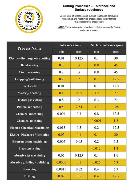
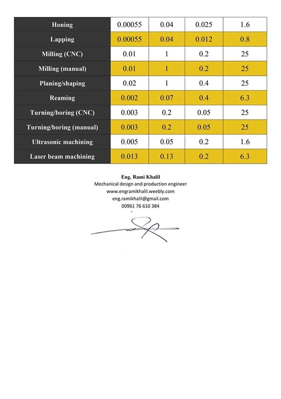
This table contains the obtained values of machining tolerance and surface roughness according to the machining or cutting process, these process collectively termed as "material removal processes".

The process (table order):
1- Electro-Discharge Wire Cutting.
2- Band Sawing.
3- Circular Sawing.
4- Cropping / Guillotining.
5- Sheet Metal.
6- Water Jet Cutting.
7- Oxyfuel Gas Cutting.
8- Plasma Arc Cutting.
9- Chemical Machining.
10- Chemical Polishing.
11- Electro-Chemical Machining.
12- Electro-Discharge Machining.
13- Electron Beam Machining.
14- Electropolishing.
15- Abrasive Jet Machining.
16- Abrasive Grinding / Polishing.
17- Broaching.
18- Drilling.
19- Honing.
20- Lapping.
21- Millimg (CNC).
22- Milling (Manual).
23- Planing / Shaping.
24- Reaming.
25- Turning / Boring (CNC).
26- Turning / Boring (Manual).
27- Ultrasonic Machining.
28- Laser Beam Machining.

Facebook:

علم القياس -|2|- علم القياس - عمليات التشغيل والقطع - جدول التسامحات وخشونة الأسطح...

Posted by Eng. Rami Khalil on Monday, December 14, 2015
Picture
Picture
Download File
0 Comments

Additive Manufacturing - Ultrasonic Additive Manufacturing (UAM) technology:

13/12/2015

0 Comments

 
It's a technique innovated by Fabrisonic company, which is a solid-state 3D-printing process for metals that uses sound waves to merge layers of metal foil. The process produces true metallurgical bonds with full density and works with a variety of metals—including but not limited to aluminum, copper, stainless steel, and titanium.

The UAM process involves building up of solid metal objects by ultrasonically welding a succession of metal tapes into a three-dimensional shape, to create the detailed features of the resultant object. The rolling ultrasonic welding system consists of ultrasonic transducers and a (welding) horn. The vibrations of the transducers are transmitted to the disk-shaped welding horn, which in turn creates an ultrasonic solidstate weld between the thin metal tape and baseplate. The continuous rolling of the horn over the plate welds the entire tape to the plate.
​
By welding a succession of tapes, first side-by-side and then one on top of the other (making sure to stagger layers so that the seams do not overlap), it is possible to build a solid metal part. A machining operation adds features to the part, removes excess tape material. Thus, the so-called “additive manufacturing” involves both additive and subtractive steps to arrive at a final part shape.

Explaining video for the process:

Facebook:

تقنيات التصنيع بالإضافة -|14|- التصنيع بالإضافة - تقينة التصنيع بالإضافة بالأمواج فوق الصوتية (Ultrasonic Additive...

Posted by Eng. Rami Khalil on Saturday, December 12, 2015
0 Comments

Mechanics of Materials - What’s the Difference Between Stress-Strain Curves and Stiffness-Strain Curves?

9/12/2015

0 Comments

 
Engineers have long used stress-strain curves to uncover a host of material properties. The curves are created by plotting the results of tensile strength tests of material samples, putting stress (force divided by area) on the y-axis and strain (stretch divided by gage or original length) on the x-axis. Some of the key material properties the curve can reveal include the material’s elastic limit, along with the elastic and plastic ranges, the yield point, ultimate and rupture strengths, and the moduli of resilience and toughness.

Sometimes, however, engineers must interpolate between data points to get those performance figures. Often a stiffness-strain curve tensile test result defines some material properties more precisely. It puts stiffness (change in stress divided by change in strain) on the y-axis and strain on the x-axis. In effect, it graphs the slope of the stress-strain curve as a function of strain.

The two graphs show the stress-strain curve (left) and the stiffness-strain curve (right) of a low-carbon steel. On the traditional stress-strain curve, engineers must measure the slope of the initial portion of the curve to determine the stiffness. On the stiffness-strain curve, engineers directly take the y-intercept as the stiffness value.

The stiffness-strain plot used the same data as the stress-strain curve, but for the clearest representation, engineers might need to use and expanded scale. They can do this by using more data points from the test results on curved portions and parts of the graph with the features of interest. Or they can increase the number of data points by using a program that generates intermediate point as using a suitable algorithm.

Facebook:

مقاومة المواد -|1|- مقاومة المواد - ماهو الفرق بين منحنيات الإجهاد - الإنفعال ومنحنيات المتانة - الإنفعال؟...

Posted by Eng. Rami Khalil on Tuesday, December 8, 2015
Picture
Explaining video:
0 Comments

Additive Manufacturing - Self-Lubricant Sublayer Photocuring (LSPc) technology:

6/12/2015

1 Comment

 
​Founded by industrial engineers, Nexa3D has developed and patented the self-Lubricant Sublayer Photocuring (LSPc) technology, cutting down the printing time to 1 minute per centimetre while achieving highest precision. The technology seems to work similar to Continuous Liquid Interface Production (CLIP) technology -this technology was explained beforehand-, creating objects in a continuous process without layers.

Unlike conventional bottom-up 3D printing systems, LSPc interposes a transparent self-lubricating film between the bottom of the tank, the photo-curing resin and the light source. By gradually releasing a layer of oil, this enables the finished resin to solidify while suspended on the substrate. This sublayer of oil prevents newly formed layers from sticking to the build platform and eliminates the need for extraction systems used in conventional technologies.

Explaining Video for the process:

Facebook:

تقنيات التصنيع بالإضافة -|13|- التصنيع بالإضافة - تقنية المعالجة الضوئية باستخدام الطبقة الفرعية ذاتية التزييت...

Posted by Eng. Rami Khalil on Friday, December 4, 2015
1 Comment
    Picture

    Eng. Rami Khalil

    Mechanical Design and Production Engineer.

    Archives

    September 2019
    November 2018
    October 2018
    August 2018
    December 2017
    February 2016
    January 2016
    December 2015
    November 2015
    October 2015
    September 2015
    August 2015
    June 2015
    May 2015
    April 2015

    Categories

    All
    Additive Manufacturing Standardization
    Additive Manufacturing Technologies
    Automation Technologies
    Machine Design
    Manufacturing Technologies
    Mechanics Of Materials
    Metrology

    Facebook:

    Youtube:

    RSS Feed

Services

  • CNC Machine Design
  • Robotic System Design
  • Mechanical Design Services

Eng. Rami Khalil

  • About
  • Vision

Menu

  • Projects
  • Publications
  • Courses
  • Library
  • Programs
  • Documents
  • Articles
  • Topics Archive
  • Lectures
  • ​Contributions

Support

  • Contact Us
  • ​Terms of Use

SOCIAL Media

Facebook
Youtube
COPYRIGHT ©  2023 ENG. RAMI KHLIL.  ALL RIGHTS RESERVED.