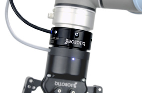
 Multi-Axis Sensor
 Q: What is a multi-axis sensor?
A: A multi-axis sensor is one that can measure forces happening in more than one plane as, for example, measurements in the x and y directions. Some multi-axis sensors can measure not just directional forces but also moments, rotational forces about an axis.
Q: How many axes can multi-axis sensors typically measure?
A: Multi-axis sensors can measure up to six axes. A six-axis device would measure x, y, z directions and moments.
Q: What applications measure forces in more than one planner direction?
A: Many such applications try to determine a vector load that must be described in terms of x, y, and z positional coordinates. Similarly, multi-axis sensors help resolve a direction or gauge inputs in multiple directions.
Q: What types of outputs can be expected?
A: Depending on the application and the magnitude of the force, typical outputs are in units of mV/V analog or they are converted to a digital output that follows a standard protocol such as FireWire or CANbus. The mV/V electrical output refers to sensor excitation at the rated load, torque or pressure. For example, the voltage output of a 2 mV/V load cell at 100 lb-rated capacity using 10-V excitation will be 20 mV at 100 lb or 0.2 mV for each pound of applied load.
Q: When do we use multi-axis sensors instead of multiple single-axis sensors?
A: A multi-axis sensor can be smaller, and occupy a smaller space envelope than multiple single-axis sensors. Moreover, its connection scheme can be simpler as well. These factors tend to reduce material costs.
Q: What choices are there in term of size and capacities?
A: It is possible to find multi-axis sensors able to detect loads of only a few grams. It is also possible to find units that can respond to loads of several thousand pounds without being crushed.
Q: What is crosstalk in multi-axis sensors?
A: When a load is applied in only one direction and there is an output in the other axes, there is said to be crosstalk between the channels. Crosstalk levels are part of the technical specs for multi-axis sensors. They are given as a percent of the channel output. Crosstalk interdependencies among force and moment axes can be compensated mathematically.
Q: How is nonlinearity defined for multi-axis sensors?
A: Nonlinearity is the maximum deviation of the calibration curve from a straight line drawn between the no-load and rated load outputs, expressed as a percentage of the rated output and measured with an increasing load.
Q: What is multi-axis sensor hysteresis?
A: Hysteresis is the maximum difference between the transducer output readings for the same applied load. One reading comes from increasing the load from zero and the other from dropping the load from the rated output. Hysteresis is usually measured at half the rated output and expressed in percent of rated output.
Q: How are multi-axis sensors mounted?
A: Because multi-axis sensors measure both moments and forces, they are sensitive to being at even a slight angle to the mounting surface. So mounting procedures must prevent even slight misalignments. Mounting surfaces must be rigid enough so that they do not warp. The general rule is that the thickness of the connection elements should be about one-third that of the transducer height. (It’s best if the contact surface deflects less than 0.005 mm under load.) The surface must also be paint-free and made of steel with a minimum hardness of 40 HRC. The stainless steel measuring body (mechanical interface) of the transducer has a minimum hardness of 42 HRC. Surface flatness should be better than 0.05 mm and surface roughness ≤ Ra 1.6. Ideally, the surface should be ground. The transducer should be centered on the structural elements and aligned using positioning pins. The angle error or the positioning tolerance should be kept below 0.1°. Finally, multi-axis sensor mounting screws should be tightened down diagonally in sequence up to the full tightening torque to keep the sensor lying flat on the mounting surface.

 RSS Feed