When a machine must provide unusual displacement or speed characteristics, don’t overlook noncircular gears. These oddly-shaped gears can fulfill several types of special motion requirements, and one of them may be the best solution for your application.
Why thease gears?
Various mechanical systems, such as cams and linkages, can provide special motion requirements, but noncircular gears often represent a simpler, more compact, or more accurate solution.
Servo systems may also be able to do the job, and they can be programmed to handle changing or complex functional requirements. But they are usually more expensive. Also some companies lack the expertise to solve problems with servo systems. Moreover, noncircular gears do offer limited ability to handle changing functional requirements. For example, you may be able to change an output function by adjusting the phase relationship between two mating noncircular gears.
Some of the more common requirements handled by noncircular gears include converting a constant input speed into a variable output speed, and providing several different constant-speed segments during an operating cycle. Other applications require combined translation and rotation or stop-and-dwell motion. Here are a few examples that may stimulate some ideas about your own applications.
Variable speed
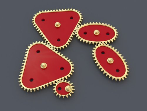
Several types of noncircular gears generate variable output speeds, particularly elliptical gears. Other, less commonly used types are triangular and square gears.
Elliptical:
An ellipse is defined by a set of points such that the sum of the distances from two fixed points on its long axis to any point on the perimeter is a constant. This enables a set of like elliptical gears to run at a constant center distance but deliver an output speed that changes as they rotate. Elliptical gears come in two basic types: unilobe, which rotates about one of the fixed points, and bilobe, which rotates about the center. The speed-reduction (or increasing) ratio of these gears varies from 1/K to K, where K depends on the gear geometry, during each cycle of rotation. Practical values of K range up to 3 for a unilobe and up to 2 for a bilobe gear.
The largest radius of the driving gear mates with the smallest radius of the driven gear so that output speed is at its maximum. As the gears rotate, the radius of the driving gear gradually decreases and that of the driven gear increases, so speed decreases for the first ¼ revolution. Then the speed increases for the next ¼ revolution, etc. These periods of increasing or decreasing speed occur four times per revolution.
Elliptical gears are commonly used in packaging and conveyor applications.
Triangular:
A pair of triangular gears also converts constant input speed into alternating output speed. However, they have three lobes, or high points on the perimeter, rather than the two lobes in elliptical bilobe gears. As a result, triangular gears deliver six periods of speed increase or decrease per revolution, rather than four.
Square:
Gears that are square provide yet another way to produce varying output speed. These gears have four lobes, so they produce eight periods of speed increase or decrease per revolution.
Both triangular and square gears are limited to a smaller range of speed ratios than with elliptical gears.
Constant-speed segments
Where an application requires several constant-speed periods within a cycle, multispeed gears may be the answer. These gears make the transition between speeds by using special function segments on the gear perimeter, usually sinusoidal, between the constant-speed sections. Typically, the input and output gears are different.
Translation and rotation
For applications requiring both translational and rotational motion, certain gears serve as cam substitutes. These cam gears are often used in labeling machines. The cam gear duplicates the shape of a part to be labeled and a cam-following rack carries the labeling device at a constant surface speed. In welding applications, a cam gear simulates the shape of a part to be welded and a follower carries a welding torch at a constant speed to ensure uniform weld application.
Stop-and-dwell motion
Some machines must provide either stop-and-dwell, or reverse motion with a constant input speed. This is achieved by combining noncircular gears with round gears and a differential (epicyclic gear train). Using round gears with different ratios gives such an arrangement the flexibility of providing either stop-anddwell or reverse motion.
Stop-and-dwell motion is common in indexing mechanisms, where gears are used rather than cam or Geneva mechanisms. Reverse motion is required where a transfer device must operate between two locations. Here, a noncircular gear arrangement is usually simpler than a commonly used linkage assembly. Despite their flexibility, such arrangements tend to be expensive.
Typical applications
These examples show how noncircular gears solve manufacturing problems.
Sealing head:
A heat-sealing device seals the tops of containers on a constant- speed conveyor. It must maintain contact for a short period of time (less than 1 sec) without slippage between the sealing head and container. A traditional approach is to install an indexing device that stops the conveyor while sealing occurs. Or, if the conveyor can’t be stopped, a cam and linkage device or electronic servo is used.
A simple solution involves mounting the sealing head on a crank mechanism driven by elliptical gears which let the head stay in contact with the container momentarily. A varying output speed provided by the gears lets the sealing head follow the container without slippage and then return for the next container.
Rotary cutoff knife:
A rotary knife cuts material on a conveyor to different lengths while the conveyor runs at a fixed speed. To cut material of different lengths without changing the conveyor speed would require using different knife sizes (diameters) and changing the knife speed.
One solution is to drive the knife with elliptical or multispeed gears. Changing the input gear speed with respect to conveyor speed changes the length of material that is cut. Adjusting the phasing between gears relative to the cutoff point causes the knife to match the conveyor speed.
Why thease gears?
Various mechanical systems, such as cams and linkages, can provide special motion requirements, but noncircular gears often represent a simpler, more compact, or more accurate solution.
Servo systems may also be able to do the job, and they can be programmed to handle changing or complex functional requirements. But they are usually more expensive. Also some companies lack the expertise to solve problems with servo systems. Moreover, noncircular gears do offer limited ability to handle changing functional requirements. For example, you may be able to change an output function by adjusting the phase relationship between two mating noncircular gears.
Some of the more common requirements handled by noncircular gears include converting a constant input speed into a variable output speed, and providing several different constant-speed segments during an operating cycle. Other applications require combined translation and rotation or stop-and-dwell motion. Here are a few examples that may stimulate some ideas about your own applications.
Variable speed
Several types of noncircular gears generate variable output speeds, particularly elliptical gears. Other, less commonly used types are triangular and square gears.
Elliptical:
An ellipse is defined by a set of points such that the sum of the distances from two fixed points on its long axis to any point on the perimeter is a constant. This enables a set of like elliptical gears to run at a constant center distance but deliver an output speed that changes as they rotate. Elliptical gears come in two basic types: unilobe, which rotates about one of the fixed points, and bilobe, which rotates about the center. The speed-reduction (or increasing) ratio of these gears varies from 1/K to K, where K depends on the gear geometry, during each cycle of rotation. Practical values of K range up to 3 for a unilobe and up to 2 for a bilobe gear.
The largest radius of the driving gear mates with the smallest radius of the driven gear so that output speed is at its maximum. As the gears rotate, the radius of the driving gear gradually decreases and that of the driven gear increases, so speed decreases for the first ¼ revolution. Then the speed increases for the next ¼ revolution, etc. These periods of increasing or decreasing speed occur four times per revolution.
Elliptical gears are commonly used in packaging and conveyor applications.
Triangular:
A pair of triangular gears also converts constant input speed into alternating output speed. However, they have three lobes, or high points on the perimeter, rather than the two lobes in elliptical bilobe gears. As a result, triangular gears deliver six periods of speed increase or decrease per revolution, rather than four.
Square:
Gears that are square provide yet another way to produce varying output speed. These gears have four lobes, so they produce eight periods of speed increase or decrease per revolution.
Both triangular and square gears are limited to a smaller range of speed ratios than with elliptical gears.
Constant-speed segments
Where an application requires several constant-speed periods within a cycle, multispeed gears may be the answer. These gears make the transition between speeds by using special function segments on the gear perimeter, usually sinusoidal, between the constant-speed sections. Typically, the input and output gears are different.
Translation and rotation
For applications requiring both translational and rotational motion, certain gears serve as cam substitutes. These cam gears are often used in labeling machines. The cam gear duplicates the shape of a part to be labeled and a cam-following rack carries the labeling device at a constant surface speed. In welding applications, a cam gear simulates the shape of a part to be welded and a follower carries a welding torch at a constant speed to ensure uniform weld application.
Stop-and-dwell motion
Some machines must provide either stop-and-dwell, or reverse motion with a constant input speed. This is achieved by combining noncircular gears with round gears and a differential (epicyclic gear train). Using round gears with different ratios gives such an arrangement the flexibility of providing either stop-anddwell or reverse motion.
Stop-and-dwell motion is common in indexing mechanisms, where gears are used rather than cam or Geneva mechanisms. Reverse motion is required where a transfer device must operate between two locations. Here, a noncircular gear arrangement is usually simpler than a commonly used linkage assembly. Despite their flexibility, such arrangements tend to be expensive.
Typical applications
These examples show how noncircular gears solve manufacturing problems.
Sealing head:
A heat-sealing device seals the tops of containers on a constant- speed conveyor. It must maintain contact for a short period of time (less than 1 sec) without slippage between the sealing head and container. A traditional approach is to install an indexing device that stops the conveyor while sealing occurs. Or, if the conveyor can’t be stopped, a cam and linkage device or electronic servo is used.
A simple solution involves mounting the sealing head on a crank mechanism driven by elliptical gears which let the head stay in contact with the container momentarily. A varying output speed provided by the gears lets the sealing head follow the container without slippage and then return for the next container.
Rotary cutoff knife:
A rotary knife cuts material on a conveyor to different lengths while the conveyor runs at a fixed speed. To cut material of different lengths without changing the conveyor speed would require using different knife sizes (diameters) and changing the knife speed.
One solution is to drive the knife with elliptical or multispeed gears. Changing the input gear speed with respect to conveyor speed changes the length of material that is cut. Adjusting the phasing between gears relative to the cutoff point causes the knife to match the conveyor speed.

 RSS Feed