ENG. RAMI KHALIL
  • Main Page
  • Vision
  • About Eng. Rami Khalil
  • Services
  • Projects
  • Art of Engineering
  • Publications
  • Courses
  • Library
  • Programs
  • Documents
  • Articles
  • Topics Archive
  • Lectures
  • Contributions
  • Contact Us

Hybrid 3D Modeling:

30/12/2015

0 Comments

 
Picture
Over the years, CAD systems have been evolved to serve as a link to reduce lead times and allow manufacturers to bring their products to the market faster. Neverthelesss, a combination of multiple approaches are utilized to effectively develop product designs with reduced lead time.

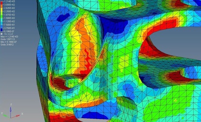
In many cases, manufacturing problems can be solved using computer CAD models and simulations; however, several cases can be best examined through physical tests.

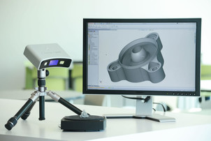
Considering product design stage, CAD modeling is usually the approach engineers use; however, utilizing 3D scanning alongside can drastically reduce the modeling time required, which in turn can decrease the product development schedules.

Leading scanning software can be utilized to convert the point cloud data into a polygon model, which can then be used to create NURBS surface model to be utilized further in any modern 3D CAD system such as SolidWorks or Inventor.

The hybrid 3D modeling approach (utilizing 3D CAD and 3D scanning together) can provide multiple benefits over conventional 3D modeling:
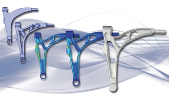
  • Replicating existing geometries becomes easier by coupling 3D measurement and CAD to build parametric models. The resulting time required to build the model can be reduces drastically. Complex models can be developed in hours that would otherwise require days or weeks through conventional modeling.
  • Complex geometries can be developed quicker as compared to conventional CAD modeling. Since through 3D scanning, complex shapes can be produced easily, the time required to manually measure the dimensions and tweak the design using CAD tools can be eliminated, reducing the development time significantly.
  • Existing CAD system can be leveraged rather than investing in new systems, allowing manufacturers to work on a familiar platform that most employees are comfortable to work with. This prevents manufacturers from investing in new CAD systems and figure out new possibilities with the existing one.
  • Developing a CAD model through digital shape sampling and processing is much more accurate then measuring the dimensions manually, reducing the possibility of errors in the 3D model being developed.
  • Lead time required to develop the digital model is reduced considerably, improving the overall product development efficiency and providing the manufacturers the ability to bring products to the market faster.

The digital shape sampling and processing (DSSP) approach helps leverage the capabilities of existing CAD systems and simultaneously assists in reducing the design time required.

Incorporating the hybrid modeling approach for complex geometry modeling in usual reverse engineering projects can infuse new capabilities in existing CAD systems and leverage existing workflows to perform product designing more productively.

0 Comments

Topology Optimization:

22/12/2015

0 Comments

 
Picture
Product cost is one of the prominent factors that manufacturers strive to reduce through evaluating number of design alternatives. It is for this reason why simulation tools are being extensively exploited, so that conventional design can be altered to an extent where products can be developed competitively in terms of price and quality.

As such, topology optimization is being increasingly applied through finite element analysis by most of the manufacturers today, helping them in developing lighter and stronger products. While the major cost function in any product is its mass due to the amount of material invested, topology optimization as a part of product design optimization for manufacturers helps them in achieving better design alternatives, requiring less material that reduces weight and allows manufacturers a room to price the product more competitively.

However, topology optimization when not applied correctly can lead to a drastic failure of the design and can hamper the brand value of the organization. It is therefore a tool that requires a broad understanding of the constraints and load cases that would affect the product design and development. Failing to consider even a single constraint can cause the design to fail and mess up all the cost optimization goals, which were actually set to meet market requirements.

Factors to Consider While Performing Topology Optimization:

To perform topology optimization, it is important to figure out design variables and constraints for the product under consideration. Also, the cost function is required to be defined to optimize the structure and figure out how good the design is.

Cost function could be reducing the mass, improving stiffness or maximizing stress resistance. However, reducing the cost function requires also the identification of design variables from where the reduction can be achieved. It could be possible to achieve optimized structure design by reducing its thickness, length or other design variable. These variables however are defined considering the constraints that put a limit on the extent to which the variable can be optimized. An example could be maximum stress and strain limits a structure or material can withstand.

Failing to realize any variable or constraint can lead to an under designed product that would fail prematurely. It is the reason why majority of the designers prefer not to use topology optimization. However, when done properly, it could reduce the cost to a significant level.

Executing Topology Optimization:

Topology optimization through finite element solvers is usually performed using gradient based algorithms that calculate the local minimum (a value beyond which the design will be invalid) at each element.

To perform the simulation run, following process is usually followed:
  • Select the most sensible cost function such as Mass of the structure, which is most usually the choice in optimization.
  • Figure out the variables that software is allowed to change and maximum limit of the change.
  • Find out all the possible ways for the structure to fail, i.e. ways through which the requirement of the design is not met.
  • Create different load cases for failure modes (e.g. static load, buckling load, etc.)
  • Define the constraints for each load case to specify when the structure will not be considered as valid. (e.g. high stresses or low factor of safety)
  • Define the maximum number of allowable cycles and maximum change allowed per cycle.

The optimization solver can then be initiated to solve the equations through finite element approach and results can be visualized. The basic topology results however are not clear as it erodes the material envelope to find the stiffest shape for all the load cases. Thus, the structure design can be improved using the eroded shape as a guide to develop a smooth geometry.

The finalized design should again be simulated and change in the variables should be compared to the previous shape. If the result is unacceptable, the load cases are required to be redefined and the procedure has to be repeated until the variable values are within the permissible range.

The topology optimization approach can be utilized to build highly economical products without much effort. Lighter and stronger products mean lower development costs for manufacturers and better acceptance rate from the consumer.

Applications of topology optimization are many, it is however important to know the sensitivity of the approach that requires considering all the design variables and constraints to avoid catastrophic failure.
0 Comments

How trustworthy are the results obtained through Finite Element Analysis - FEA?

19/12/2015

2 Comments

 
PictureExample of FEA Resuts
​Finite element analysis has always been used as a third dimension in product testing apart from experimental and analytical tests. The reason why FEA alone is not employed as a standard testing tool is primarily because it is an approximation of the partial differential equations and often consists of residuals that always keep the results from being 100% accurate.

However, FEA cannot be neglected as it helps in achieving comprehensive product behavior under loading even for complex geometries for which approximations are better than knowing nothing. The validity of FEA results however is purely a judgment that is based on the knowledge of the analyst performing the simulation. It is purely his expertise and accurate application of boundary conditions with required assumptions that yields a meaningful result through FEA approach.

Any FEA solver or a software package available today incorporates number of functions and variables which include force, mass, velocity, acceleration, heat flux, stress-strain, displacement and other dynamic loads, with each load case requiring a separate analysis.

However, modern simulation tools have become much easier allowing non-experts to easily model the problem. The results obtained however are required to be justified. An inexperienced engineer might consider the results valid whereas an experienced analyst might consider adding few more elements across critical regions of the geometry and refine the results further.

While FEA helps in reducing number of prototyping trials and manual calculations, the results are still required to be verified with a physical experiment to ensure the solvers reliability. It is quite easy to build a neat and colorful FEA model through several computational iterations but with no meaningful value. It is always good to perform simple hand calculations in the beginning before going for a simulation run.

Later, when the FEA results show dramatic increase in the values, it can be easily identified that something is wrong with the simulation or the boundary conditions might not have been defined properly.

Regions with complex geometry such as edges, chamfers, holes or curves can be easily neglected by an inexperienced engineer. An expert would rather consider the ones critical to the design aspect and apply fine mesh on those regions to ensure that the physics are captured accurately.

It is also crucial to carry out mesh sensitivity analysis by performing same FEA load case with different mesh quality and element types to realize that the solution has the potential to give accurate results without further mesh refinement required.

When in the right hands, FEA can save months in the product design and development stage by providing required information early. Prototyping trials can be reduced considerably with a subsequent reduction in development costs.

However, it is important to realize that the tool will only be as good as the operator using it. It is thus the ability and experience of the analyst that decides the quality of FEA results and not the expensiveness of the software package that promises accuracy.

2 Comments

Sorting out Sensors:

1/12/2015

0 Comments

 
Proximity, capacitance, and photoelectric sensors play an important role in the robust control of industrial machines. To select the proper sensor for a given job, engineers should start with a clear understanding of the application requirements, sensor specifications, and installation demands. Here’s a look at the importance of factors like sensing distance, environmental effects, connectivity concerns, and mounting options.

Sensing Basics:

All sensor applications have certain specific needs, and a good place to start when selecting a sensor is to review basic sensor selection criteria. Users need to determine:
  • Targets the sensor must detect.
  • Objects and backgrounds the sensor must not detect.
  • The best sensing technology for detecting only the targets.
  • Available mounting space and restraints.
  • Sensor form factor.
  • Electrical requirements.
  • Cabling requirements.
  • Mounting requirements.
Engineers must first understand and identify targets and backgrounds. Targets are the objects, parts, ink marks, or empty spaces the sensor must detect. Backgrounds are everything else that should not be detected, and sometimes take the same form as the aforementioned targets. For example, the target could be a brown cardboard box traveling on a conveyor, while the background might be an empty space or a worker walking next to the conveyor.

Next, select the best type of sensor that detects the target while ignoring the background. The installation environment and other constraints may affect this decision.
Key differences in sensing technology drive selection as engineers must consider what is sensed and how it is being sensed. Sensing distance and environmental effects also help determine the final choice of sensor.

Proximity Sensors:

Picture
Inductive proximity sensors generate a magnetic field from an inductive coil, which is disturbed when a ferrous target is present. Standard inductive sensors only detect ferrous objects, but they do so consistently and repeatably with little interference from ambient elements. Unfortunately, these sensors only detect metal and some metals, such as stainless steel, reduce sensing distance.
​
Proximity sensors have sensing ranges from 1 to 120 mm, with longer ranges requiring larger sensors. For example, sensors with a sensing range of 2 to 25 mm are supplied in 8 to 30 mm diameter housings, respectively.

Photoelectric Sensors:

Picture
Photoelectric sensors use light to detect objects. They emit and receive light at certain wavelengths: infrared, visible red, or laser light. The emitter and receiver may be in one housing (common in diffuse and retroreflective configurations) or in two separate housings (common in through-beam configurations). Photoelectric sensing is quite versatile, as these sensors can detect very small objects made of many different material types at considerable distances.

However, photoelectric sensors can be influenced by ambient conditions, and many require programming during installation to optimize operation. These sensors are the most sensitive to dirt and debris, which can cause false triggers by interfering with the operation of the emitter and receiver.
​
On the other hand, photoelectric sensors have the broadest sensing range. With laser light they can detect objects just a few microns thick. A photoelectric laser sensor can also be configured to detect a target whether positioned close to or far from the target, due to the power of a focused laser beam. Less-expensive infrared and visible red photoelectric sensors have sensing ranges from 100 mm with diffuse beam, and up to 50 m with through-beam.

Capacitive Sensors:

Picture
Capacitive sensors essentially look for the dielectric or density in a sensing area. They can detect almost any object, but fare better with high-density objects. Capacitive sensors are ideal for sensing levels of liquids or bulk dry materials. The switching threshold can be adjusted to “tune out” items that should not be detected—a plastic tank wall or a cardboard box, for example. These sensors can be influenced by ambient materials and have a relatively small sensing range.
​
Capacitive sensors generally have sensing ranges less than 60 mm, although this distance is strongly influenced by the target’s dielectric value.

Connection Options:

Sensors commonly connect to controllers such as PLCs or PLC-based PACs. Electrically, most modern sensors use low-voltage dc control power, typically 24 V dc; 120 V ac is also available. Discrete sensors primarily provide solid-state positive-to-negative (PNP) or negative-to-positive (NPN) switching outputs, and analog sensors commonly have 0- to 10-V or 4- to 20-mA outputs.

Most sensors require a specific switching type, either PNP or NPN. However, some sensors can be modified for either type, as well as for other options. These sensors let programming, switch configuration, or wiring of the device determine the switching type at the time of installation. Similar options are available for normally open and closed switching states.

Whether the connection is to the sensor or a photoelectric sensor amplifier, a variety of cabling options are available. Prewired cables have the cable molded into the sensor. This usually is the least expensive option and simplifies purchasing. Another benefit is the molded cable works well with small sensors as it permits mounting in tight spaces. However, prewired cables are restricted to available lengths for the most part, approximately 2 to 5 meters. When the sensor fails, the cable must be rerun and secured, increasing installation time.

Quick-disconnect cables have become an extremely popular choice. These cables let technicians add a cable, of any length or material, independent of the sensor. Once installed, changing failed sensors is quick and simple. But while quick-disconnect cable options are plentiful, they can add cost and complicate the purchasing process.
​
Quick-disconnect plugs are becoming an industry standard. Precut 2- to 15-m length cables are typically available in axial and right-angle configurations, with M8 or M12 size screw-lock connectors on one end and flying leads at the other end. Regardless of the sensor selected, the specified cable must work with the electrical configuration of the sensor. For example, M8 and M12 connectors commonly come in 3- and 4-pole configurations for sensors. The number of pins must also be carefully specified.

Application Guidelines:

When properly specified, most sensors can function in a variety of applications. However, although there is much overlap in sensor application, there are cases where one sensor technology works better than the others.

For example, sensing end-of-travel of a pneumatic or motor-driven actuator and sensing metal objects are common applications for an inductive proximity switch. Once a premium product, these simple and robust devices are some of the most commonly used today due to more competitive pricing. If there is a ferrous target within a close distance, the inductive proximity sensor is the best choice due to its rugged design and minimal effects from outside influence. Common uses include detecting presence of a metal part, conveyor pallet, or gear teeth; or detecting actuator movement and home position.

​Photoelectric sensors are versatile sensors which work well in a wide range of applications. Common uses include sensing part presence in a fixture or sensing parts on a conveyor. Using the precision of a laser, even small printed circuit board components can be detected. It is also possible to measure height of an object from meters away. Detecting print marks on a high-speed labeling machine or counting bottles on a filling line are common uses for standard photoelectric sensors. However, placing the sensor under water or where it may be splashed with oil or process fluid can cause sensing issues.

A key feature of capacitive sensors is the ability to see through paper, plastic, and cardboard boxes. These sensors can also sense liquid presence, or detect an object traveling through a liquid. Counting machined brass fittings passing the sensor while submerged in cutting fluid is feasible with a capacitive sensor, but not with other types. This adjustability permits detection of a variety of liquid and solids, including water, oil, chemicals, powders, and grains.

Sensing liquid level through tank walls, sight glasses, or in a mounting well for both high and low level are other primary applications for capacitive sensors. When mounted closely enough, the capacitive sensor can also detect fill level in boxes or opaque bottles.

Each of these sensing technologies affects sensing range (distance). While a longer sensing range may seem like a better choice, consider the application carefully to minimize false triggering of a sensor.

comparison:

Picture
0 Comments
    Picture

    Eng. Rami Khalil

    Mechanical Design and Production Engineer.

    Archives

    November 2019
    May 2019
    November 2018
    October 2018
    May 2016
    January 2016
    December 2015
    November 2015
    February 2014
    January 2014

    Categories

    All
    Addictive Manufacturing
    Additive Manufacturing Standardization
    Automation Control
    Machine Design
    Manufacturing Processes
    Material Science
    Product Design And Development
    Robotics
    WaterJet Technology

    Facebook:

    Youtube:

    RSS Feed

Services

  • CNC Machine Design
  • Robotic System Design
  • Mechanical Design Services

Eng. Rami Khalil

  • About
  • Vision

Menu

  • Projects
  • Publications
  • Courses
  • Library
  • Programs
  • Documents
  • Articles
  • Topics Archive
  • Lectures
  • ​Contributions

Support

  • Contact Us
  • ​Terms of Use

SOCIAL Media

Facebook
Youtube
COPYRIGHT ©  2023 ENG. RAMI KHLIL.  ALL RIGHTS RESERVED.