ENG. RAMI KHALIL
  • Main Page
  • Vision
  • About Eng. Rami Khalil
  • Services
  • Projects
  • Art of Engineering
  • Publications
  • Courses
  • Library
  • Programs
  • Documents
  • Articles
  • Topics Archive
  • Lectures
  • Contributions
  • Contact Us

Multi-Axis Sensors - Frequently Asked Questions:

26/5/2016

0 Comments

 
PictureMulti-Axis Sensor
Q: What is a multi-axis sensor? 
A: A multi-axis sensor is one that can measure forces happening in more than one plane as, for example, measurements in the x and y directions. Some multi-axis sensors can measure not just directional forces but also moments, rotational forces about an axis.

Q: How many axes can multi-axis sensors typically measure? 
A: Multi-axis sensors can measure up to six axes. A six-axis device would measure x, y, z directions and moments.
Q: What applications measure forces in more than one planner direction? 
A: Many such applications try to determine a vector load that must be described in terms of x, y, and z positional coordinates. Similarly, multi-axis sensors help resolve a direction or gauge inputs in multiple directions.

Q: What types of outputs can be expected? 
A: Depending on the application and the magnitude of the force, typical outputs are in units of mV/V analog or they are converted to a digital output that follows a standard protocol such as FireWire or CANbus. The mV/V electrical output refers to sensor excitation at the rated load, torque or pressure. For example, the voltage output of a 2 mV/V load cell at 100 lb-rated capacity using 10-V excitation will be 20 mV at 100 lb or 0.2 mV for each pound of applied load.

Q: When do we use multi-axis sensors instead of multiple single-axis sensors? 
A: A multi-axis sensor can be smaller, and occupy a smaller space envelope than multiple single-axis sensors. Moreover, its connection scheme can be simpler as well. These factors tend to reduce material costs.

Q: What choices are there in term of size and capacities? 
A: It is possible to find multi-axis sensors able to detect loads of only a few grams. It is also possible to find units that can respond to loads of several thousand pounds without being crushed.

Q: What is crosstalk in multi-axis sensors? 
A: When a load is applied in only one direction and there is an output in the other axes, there is said to be crosstalk between the channels. Crosstalk levels are part of the technical specs for multi-axis sensors. They are given as a percent of the channel output. Crosstalk interdependencies among force and moment axes can be compensated mathematically.

Q: How is nonlinearity defined for multi-axis sensors? 
A: Nonlinearity is the maximum deviation of the calibration curve from a straight line drawn between the no-load and rated load outputs, expressed as a percentage of the rated output and measured with an increasing load.

Q: What is multi-axis sensor hysteresis? 
A: Hysteresis is the maximum difference between the transducer output readings for the same applied load. One reading comes from increasing the load from zero and the other from dropping the load from the rated output. Hysteresis is usually measured at half the rated output and expressed in percent of rated output.

Q: How are multi-axis sensors mounted? 
A: Because multi-axis sensors measure both moments and forces, they are sensitive to being at even a slight angle to the mounting surface. So mounting procedures must prevent even slight misalignments. Mounting surfaces must be rigid enough so that they do not warp. The general rule is that the thickness of the connection elements should be about one-third that of the transducer height. (It’s best if the contact surface deflects less than 0.005 mm under load.) The surface must also be paint-free and made of steel with a minimum hardness of 40 HRC. The stainless steel measuring body (mechanical interface) of the transducer has a minimum hardness of 42 HRC. Surface flatness should be better than 0.05 mm and surface roughness ≤ Ra 1.6. Ideally, the surface should be ground. The transducer should be centered on the structural elements and aligned using positioning pins. The angle error or the positioning tolerance should be kept below 0.1°. Finally, multi-axis sensor mounting screws should be tightened down diagonally in sequence up to the full tightening torque to keep the sensor lying flat on the mounting surface.
0 Comments

Additive Manufacturing,Things must be known:

9/1/2016

0 Comments

 
Picture
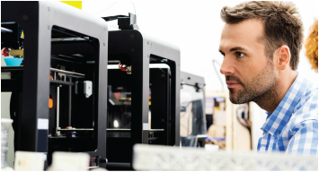
​Information and expertizes have spread all over the internet in form of videos and articles, showing how easily anyone can print the products simply through CAD modeling and pushing the print button. But, if you are into design and manufacturing, you’re probably guessing that there’s more to it.

And you’re right; there are few important things to know more about the additive manufacturing technology, if you’re seriously planning to develop products through this technology in near future.

Software for Rapid Prototyping:

​Software technology plays a crucial role in additive manufacturing process, and is constantly evolving to compliment the advancing 3D printing capabilities of the printer. The use of software spans across the additive manufacturing lifecycle right from sourcing ideas, designing the model and providing formatted data to printers, to monitoring and managing the printing process. It serves as an important link, enabling interfaces between computers and printers to allow entire 3D printing ecosystem to function efficiently.

In general, printing a part require 4 different software to ensure accuracy, reduced cost and quality. Also, special software packages are also required to convert solid geometries to lattice structures along with tools to perform simulations.

The journey from idea to the additive manufactured final part begins with sourcing the model either through rapidly growing 3D libraries or through 3D scanning techniques or through custom designs. This is followed by the design process where an exact 3D model of the product is prepared that will be printed, considering proper dimensions and geometrical accuracies. The next step is to optimize the geometry using software to suit the printing process and reduce material wastage. Finally, the software is also required to actually print the part and monitor the process to make print runs successful.

CAD Modeling Process:

​Unlike conventional modeling processes, developing 3D models for additive manufacturing requires a different approach. One of the important things to consider is the resolution of the geometry; too high resolution will consume more time to load and simultaneously print the part. On the contrary, a low-res model would develop prototype with poor quality. Moreover, the geometry to be developed is also material-sensitive.

As an example, products to be printed in plastic would require the dimensions of the holes in the design to be resized, as they would expand or contract during heating and cooling applications. Also, the geometry to be printed has to be thoroughly inspected for any open spaces and must be converted to “watertight”, to avoid errors in printing.

Design Optimization:

​Design optimization is a key to successful and cost effective utilization of additive manufacturing techniques. The purpose of using this advanced manufacturing technology is to reduce development cost and time, and thus, reducing material wastage during printing process remains a vital strategy. This requires the design engineers to understand the process of printing that requires rafts and supports to build the desired structure. Engineers have to identify a design that uses minimal support material that can also be removed easily once the part gets printed. Also, the design engineer must identify a balance between part density, strength and surface finish, and accordingly choose the material, printing speed and the used additive manufacturing technolgy.

To summarize, Right from sourcing the model, through designing and optimizing to monitoring printing process, the role of software is important across every step in the prototype or product development. Modeling methods require a good knowledge on the printing process, material to be used and the printing technology adopted.

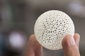
Moreover, the need to optimize the design and apply lattice structures instead of solid geometry should be considered to reduce material consumption while maintaining the required strength of the product being developed. Successfully implementing rapid prototyping to gain the benefits of cost reduction and faster development schedules require manufacturers and engineers to adopt right processes and software technologies.

As such, 3D printing technology isn’t as easy as it seems. There’s so much more to it than simply creating a CAD model and pushing the print button.
0 Comments

ASTM Committee F42 on Additive Manufacturing Technologies:

1/1/2016

2 Comments


Definition:

Picture
​ASTM Committee F42 on Additive Manufacturing Technologies was formed in 2009. F42 meets twice a year, usually in January and July, with about 70 members attending two days of technical meetings. The Committee, with a current membership of approximately 215, has up to now 4 technical subcommittees; all standards developed by F42 are published in the Annual Book of ASTM Standards, Volume 10.04.

Committee Scope:

​The promotion of knowledge, stimulation of research and implementation of technology through the development of standards for additive manufacturing technologies. The work of this Committee will be coordinated with other ASTM technical committees and other national and international organizations having mutual or related interestes.

F42 subcommittees and standards under the jurisdiction of F42:

1- Subcommittee F42.01 on Test Methods:

Current Standards:
  • F2971-13 Standard Practice for Reporting Data for Test Specimens Prepared by Additive Manufacturing.
  • F3122-14 Standard Guide for Evaluating Mechanical Properties of Metal Materials Made via Additive Manufacturing Processes.
  • ISO/ASTM52921-13 Standard Terminology for Additive Manufacturing-Coordinate Systems and Test Methodologies.

Work item under development:
  • WK49798 New Guide for Intentionally Seeding Flaws in Additively Manufactured (AM) Parts.
  • WK49229 New Guide for Anisotropy Effects in Mechanical Properties of AM Parts.
  • WK49272 New Test Methods for Characterization of Powder Flow Properties for AM Applications.

2- Subcommittee F42.04 Design:

Current Standards:
  • ISO/ASTM52915-13 Standard Specification for Additive Manufacturing File Format (AMF) Version 1.1.

Work item under development:
  • WK38342 New Guide for Design for Additive Manufacturing.
  • WK48549 New Specification for AMF Support for Solid Modeling: Voxel Information, Constructive Solid Geometry Representations and Solid Texturing.
  • WK51841 Principles of Design Rules in Additive Manufacturing.

3- Subcommittee F42.05 Materials and Processes:

Current Standards:
  • F2924-14 Standard Specification for Additive Manufacturing Titanium-6 Aluminum-4 Vanadium with Powder Bed Fusion.
  • F3001-14 Standard Specification for Additive Manufacturing Titanium-6 Aluminum-4 Vanadium ELI (Extra Low Interstitial) with Powder Bed Fusion.
  • F3049-14 Standard Guide for Characterizing Properties of Metal Powders Used for Additive Manufacturing Processes.
  • F3055-14a Standard Specification for Additive Manufacturing Nickel Alloy (UNS N07718) with Powder Bed Fusion.
  • F3056-14e1 Standard Specification for Additive Manufacturing Nickel Alloy (UNS N06625) with Powder Bed Fusion.
  • F3091/F3091M-14 Standard Specification for Powder Bed Fusion of Plastic Materials.

Work item under development:
  • WK51282 Additive Manufacturing, General Principles, Requirements for Purchased AM Parts.
  • WK51329 New Specification for Additive Manufacturing Cobalt-28 Chromium-6 Molybdenum Alloy (UNS R30075) with Powder Bed Fusion.
  • WK37654 New Guide for Directed Energy Deposition of Metals.
  • WK46188 New Practice for Metal Powder Bed Fusion to Meet Rigid Quality Requirements.
  • WK48732 New Specification for Additive Manufacturing Stainless Steel Alloy (UNS S31603) with Powder Bed Fusion.

4- Subcommittee F42.06 Environment, Health, and Safety: 
(Under development).

5- Subcommittee F42.90 Executive: 
(Under development).

6- Subcommittee F42.91 Terminology:

Current Standards:
  • F2792-12a Standard Terminology for Additive Manufacturing Technologies

7- Subcommittee F42.94 Strategic Planning:
(Under development).

8- Subcommittee F42.95 US TAG to ISO TC 261:
(Under development).
2 Comments

Hybrid 3D Modeling:

30/12/2015

0 Comments

 
Picture
Over the years, CAD systems have been evolved to serve as a link to reduce lead times and allow manufacturers to bring their products to the market faster. Neverthelesss, a combination of multiple approaches are utilized to effectively develop product designs with reduced lead time.

In many cases, manufacturing problems can be solved using computer CAD models and simulations; however, several cases can be best examined through physical tests.

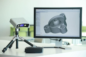
Considering product design stage, CAD modeling is usually the approach engineers use; however, utilizing 3D scanning alongside can drastically reduce the modeling time required, which in turn can decrease the product development schedules.

Leading scanning software can be utilized to convert the point cloud data into a polygon model, which can then be used to create NURBS surface model to be utilized further in any modern 3D CAD system such as SolidWorks or Inventor.

The hybrid 3D modeling approach (utilizing 3D CAD and 3D scanning together) can provide multiple benefits over conventional 3D modeling:
  • Replicating existing geometries becomes easier by coupling 3D measurement and CAD to build parametric models. The resulting time required to build the model can be reduces drastically. Complex models can be developed in hours that would otherwise require days or weeks through conventional modeling.
  • Complex geometries can be developed quicker as compared to conventional CAD modeling. Since through 3D scanning, complex shapes can be produced easily, the time required to manually measure the dimensions and tweak the design using CAD tools can be eliminated, reducing the development time significantly.
  • Existing CAD system can be leveraged rather than investing in new systems, allowing manufacturers to work on a familiar platform that most employees are comfortable to work with. This prevents manufacturers from investing in new CAD systems and figure out new possibilities with the existing one.
  • Developing a CAD model through digital shape sampling and processing is much more accurate then measuring the dimensions manually, reducing the possibility of errors in the 3D model being developed.
  • Lead time required to develop the digital model is reduced considerably, improving the overall product development efficiency and providing the manufacturers the ability to bring products to the market faster.

The digital shape sampling and processing (DSSP) approach helps leverage the capabilities of existing CAD systems and simultaneously assists in reducing the design time required.

Incorporating the hybrid modeling approach for complex geometry modeling in usual reverse engineering projects can infuse new capabilities in existing CAD systems and leverage existing workflows to perform product designing more productively.

0 Comments

Topology Optimization:

22/12/2015

0 Comments

 
Picture
Product cost is one of the prominent factors that manufacturers strive to reduce through evaluating number of design alternatives. It is for this reason why simulation tools are being extensively exploited, so that conventional design can be altered to an extent where products can be developed competitively in terms of price and quality.

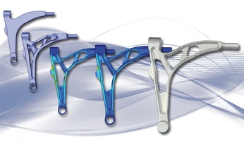
As such, topology optimization is being increasingly applied through finite element analysis by most of the manufacturers today, helping them in developing lighter and stronger products. While the major cost function in any product is its mass due to the amount of material invested, topology optimization as a part of product design optimization for manufacturers helps them in achieving better design alternatives, requiring less material that reduces weight and allows manufacturers a room to price the product more competitively.

However, topology optimization when not applied correctly can lead to a drastic failure of the design and can hamper the brand value of the organization. It is therefore a tool that requires a broad understanding of the constraints and load cases that would affect the product design and development. Failing to consider even a single constraint can cause the design to fail and mess up all the cost optimization goals, which were actually set to meet market requirements.

Factors to Consider While Performing Topology Optimization:

To perform topology optimization, it is important to figure out design variables and constraints for the product under consideration. Also, the cost function is required to be defined to optimize the structure and figure out how good the design is.

Cost function could be reducing the mass, improving stiffness or maximizing stress resistance. However, reducing the cost function requires also the identification of design variables from where the reduction can be achieved. It could be possible to achieve optimized structure design by reducing its thickness, length or other design variable. These variables however are defined considering the constraints that put a limit on the extent to which the variable can be optimized. An example could be maximum stress and strain limits a structure or material can withstand.

Failing to realize any variable or constraint can lead to an under designed product that would fail prematurely. It is the reason why majority of the designers prefer not to use topology optimization. However, when done properly, it could reduce the cost to a significant level.

Executing Topology Optimization:

Topology optimization through finite element solvers is usually performed using gradient based algorithms that calculate the local minimum (a value beyond which the design will be invalid) at each element.

To perform the simulation run, following process is usually followed:
  • Select the most sensible cost function such as Mass of the structure, which is most usually the choice in optimization.
  • Figure out the variables that software is allowed to change and maximum limit of the change.
  • Find out all the possible ways for the structure to fail, i.e. ways through which the requirement of the design is not met.
  • Create different load cases for failure modes (e.g. static load, buckling load, etc.)
  • Define the constraints for each load case to specify when the structure will not be considered as valid. (e.g. high stresses or low factor of safety)
  • Define the maximum number of allowable cycles and maximum change allowed per cycle.

The optimization solver can then be initiated to solve the equations through finite element approach and results can be visualized. The basic topology results however are not clear as it erodes the material envelope to find the stiffest shape for all the load cases. Thus, the structure design can be improved using the eroded shape as a guide to develop a smooth geometry.

The finalized design should again be simulated and change in the variables should be compared to the previous shape. If the result is unacceptable, the load cases are required to be redefined and the procedure has to be repeated until the variable values are within the permissible range.

The topology optimization approach can be utilized to build highly economical products without much effort. Lighter and stronger products mean lower development costs for manufacturers and better acceptance rate from the consumer.

Applications of topology optimization are many, it is however important to know the sensitivity of the approach that requires considering all the design variables and constraints to avoid catastrophic failure.
0 Comments
<<Previous
Forward>>
    Picture

    Eng. Rami Khalil

    Mechanical Design and Production Engineer.

    Archives

    November 2019
    May 2019
    November 2018
    October 2018
    May 2016
    January 2016
    December 2015
    November 2015
    February 2014
    January 2014

    Categories

    All
    Addictive Manufacturing
    Additive Manufacturing Standardization
    Automation Control
    Machine Design
    Manufacturing Processes
    Material Science
    Product Design And Development
    Robotics
    WaterJet Technology

    Facebook:

    Youtube:

    RSS Feed

Services

  • CNC Machine Design
  • Robotic System Design
  • Mechanical Design Services

Eng. Rami Khalil

  • About
  • Vision

Menu

  • Projects
  • Publications
  • Courses
  • Library
  • Programs
  • Documents
  • Articles
  • Topics Archive
  • Lectures
  • ​Contributions

Support

  • Contact Us
  • ​Terms of Use

SOCIAL Media

Facebook
Youtube
COPYRIGHT ©  2023 ENG. RAMI KHLIL.  ALL RIGHTS RESERVED.