ENG. RAMI KHALIL
  • Main Page
  • Vision
  • About Eng. Rami Khalil
  • Services
  • Projects
  • Art of Engineering
  • Publications
  • Courses
  • Library
  • Programs
  • Documents
  • Articles
  • Topics Archive
  • Lectures
  • Contributions
  • Contact Us

Profile Shifted Gears

16/11/2019

0 Comments

 
Picture
Avoiding an undercut with a standard gear (standard pressure angle of 20°) requires a minimum number of teeth of 17. If gears are nevertheless to be manufactured below the limit number of teeth (e.g. because a certain transmission ratio is to be achieved), the undercut must be avoided in another way. For this purpose, a so-called profile shift can be used.

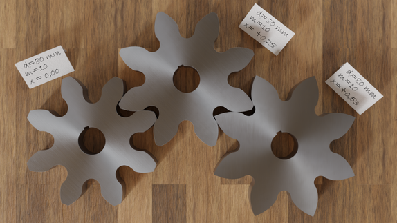
With a profile shift, the tool profile is shifted outwards by a certain amount during gear cutting. The animation below shows the effects of a profile shift on the tooth form of a gear with 8 teeth. It becomes clear that as the profile shift increases, the undercut becomes smaller and can even be completely avoided.

Even if the tooth shapes differ from each other, the teeth can still mesh with each other. Profile shifted gears (also called corrected gears) can therefore be easily paired with non-profile shifted gears (so-called standard gears) as long as they are manufactured with the same tool and therefore have the same module.

Even if this may not seem so at first glance, a profile shift has no influence on the shape of the tooth flank itself. All profile shifted gears use the same involute for the tooth shape compared to their corresponding standard gears. Only another part of the same involute is used. This becomes clear when the tooth flanks of the gears with different profile shifts are placed on top of each other.
Note that the base circle for constructing the involute is determined solely by the flank angle of the tool profile (standard pressure angle) during gear cutting. And since the angle of the cutting edges does not change with a profile shift, the base circle and thus the involute do not change either.

The radius of curvature of the involute increases with increasing length, i.e. the further away the involute is from the base circle, the larger the radius of curvature is and the less strongly it is therefore curved. The flank shape at this more distant area is rather “flat” than “pointed”. The smaller curvature leads to a larger contact surface of the flanks, which reduces the pressure accordingly (less Hertzian contact stress). This reduces the stress on the flanks and thus increases the flank load-bearing capacity.

The animation below shows the profile shift of a gear with 6 teeth to avoid an undercut. In this case, the thickness of the tip tooth even decreases so much that the involutes taper before the shifted tip diameter is reached. The increase of the tip circle radius by the amount of the profile shift cannot therefore be maintained in this case, the tip diameter is inevitably shortened.

In addition, the tip circle would have to be shortened again to at least 0.2 times the module in order to increase the thickness of the tip tooth. However, such a large reduction of the tip circle would also result in a correspondingly large reduction of the line of action. Involute gears with fewer than 7 teeth should therefore be avoided by any means.

With corrected gears, an extended part of the involute is used as tooth flank compared to standard gears. When meshing with another gear, this further curved part of the involute requires the center distance to be increased by the amount of the profile shift V= x⋅m.

In summary, it can be stated that a profile shift is always applied if:
​
  • An undercut is be avoided,
  • The tooth strength must be increased,
  • The surface pressure at the flanks is to be decreased, or
  • The center distance must be adjusted.


0 Comments

GlasS-Metal Welding

28/5/2019

0 Comments

 
Picture
Traditionally it has been very difficult to weld together dissimilar materials like glass and metal due to their different thermal properties as the high temperatures and highly different thermal expansions involved cause the glass to shatter.
 
Currently, glass and metal are often held together with adhesives, but that process is messy, and parts can gradually move out of place. Additionally, “organic chemicals from the adhesive can be gradually released and can lead to reduced product lifetime
 
Instead of adhesives, the method Hand and his research team from Heriot-Watt university used to join glass and metal is a technique of recent interest called ultrafast laser micro-welding. Ultrafast laser micro-welding involves aiming laser pulses at the interface between two materials in quick succession so that heat accumulates at the interface and leads to localized melting. When the laser pulses stop and the material re-solidifies, strong and robust bonds form between the materials along the interface.
So far, the majority of research on ultrafast laser micro-welding has focused on similar or slightly dissimilar materials, while research on highly dissimilar materials has concentrated on bonding glass and silicon.

For research on glass and metal welding, Hand and his team explain these previous studies were limited to proof-of-principle demonstrations involving specific material combinations and limited systematic studies. That is why the researchers “aim to move ultrafast micro-welding closer to an industrially viable technique through a systematic study of the parameter space for welding and demonstrating accelerated lifetime survivability,” as they explain in their paper.

However, due to the brittle nature of glass, creating enough samples to produce statistically relevant tests of all parameters was impractical—each process parameter set would require at least 20 samples! So, the researchers chose to focus only on pulse energy and focal plane for this study.
Even just focusing on pulse energy and focal plane, though, would require more than 1,000 individual welds. To limit the number of required samples, the researchers carried out two tests for each pair of parameters to create a parameter map. They used the map to identify regions of interest to run full, 20-sample tests. After running these tests, they identified an “optimized” set of parameters for accelerated lifetime testing.

While the Heriot-Watt press release states various optical materials like quartz, borosilicate glass, and sapphire were all successfully welded to metals like aluminum, titanium, and stainless steel, the actual paper focuses on welding two specific glasses [Spectrosil 2000 (SiO2) and Schott N-BK7 (BK7)] to 6082 aluminum alloy (Al6082).

When discussing the results, one somewhat counter intuitive finding the researchers highlight is that minor cracking around the melt volume (particularly in the glass) indicates a good weld. Cracking is due to the significant difference in thermal expansion between glass and metal—through cracking, glass relieves itself of the thermal stress that occurs during cooling. “[This cracking] does not indicate a reduction in the weld strength,” the authors stress.

In the future, the authors note that further work in thermal compensation, either through interlayers or surface patterning to relieve thermal stress, is needed to develop a reliable welding process, “particularly for material combinations with a large mismatch of thermal expansion, e.g., Al6082–SiO2.”
0 Comments

Auxetic Materials

30/11/2018

1 Comment

 
Picture
Auxetic materials are a class of meta-materials which exhibit negative Poisson’s Ratio (Meta-materials are a class of man-made materials that have been specially and artificially engineered to contain small inhomogeneities which alter the properties on a macroscopic level). They have been known for over a hundred years but have only gained attention in recent decades. They can be single molecules, but more often they consist of an engineered material with a particular structure on the macroscopic level. Auxetic materials can occur in nature, but they are very rare. For example, some rocks and minerals demonstrate auxetic properties as does the skin on a cow’s teats.

Auxetics are created by modifying the macrostructure of the material so that it contains hinge-like features which change shape when a force is applied. If a tensile force is applied the hinge-like structures extend, thus causing lateral expansion. If a compressive force is applied the hinge-like structures fold even further causing lateral contraction.

A common analogy used to describe the behavior of auxetic materials is to consider an elastic cord with an inelastic string wrapped around it. When a tensile force is applied the inelastic material straightens at the same time as the elastic cord stretches, thus effectively increasing the volume of the structure.
Auxetic materials are often based on foam structures and as such they have a relatively low density. It is this open cell structure which can be modified to give the desired properties.

The unusual properties of auxetic materials mean that they are relatively resistant to denting. When an auxetic is hit the compression caused by the impact results in the material compressing towards the point of the impact, thus becoming much denser and resisting the force. Auxetic materials are also more resistant to fracture; they expand laterally as a force is applied and this closes up potential cracks in the material before they start to grow. The main drawback of these materials is that they are often too porous, not dense enough or not stiff enough for load bearing applications and when these properties are adjusted the auxetic behavior tends to be reduced. Applications of these materials therefore often rely on a compromise of properties.

Auxetic materials can essentially be made in two different ways. In the top-down approach everyday polymers are manipulated to give the desired structure and properties. In the bottom-up approach the material is built up from scratch, molecule by molecule, allowing them to be engineered on a very small scale. In both cases the objective is to create a repeating pattern of building blocks or cells which contain the necessary hinge-like features.

There have been many suggested uses for auxetic materials, but most of these have yet to come to fruition commercially. These materials can be difficult to process on a large scale, making industrial manufacture difficult. Some potential areas for use are described below:

Biomedical applications
Many of the materials that are currently used in medical applications can be processed to exhibit auxetic properties. It has been suggested that auxetic materials could be used to dilate blood vessels during heart surgery. A piece of auxetic foam, possibly made from PTFE would be inserted into the blood vessel and then tension applied to this to cause lateral expansion and open out the vessel. Auxetics could also be used in surgical implants and prosthesis and for the anchors used to hold sutures, muscles and ligaments in place.

Filters
Traditional filters can be incredibly difficult to clean, leading to them being thrown away prematurely. A filter made from an auxetic foam could be cleaned much more easily by simply applying a tensile force to open up the pores. Once clean the force can be removed and the filter refitted.

Auxetic fibers
This is one area which does show real potential for exploitation. The key here is the development of a continuous process for developing auxetic materials in the form of fibers. The resulting fibers could be used in monofilament or multifilament form and could be knitted or woven together to make cloth. It has been suggested that these fabrics could be used in crash helmets, body armor and sports clothing where their dent and fracture resistance would be exploited.

Auxetic materials could also be added to metallic materials such as steels to create composites with improved resistance to cracking under shear strain (twisting).
1 Comment

Non-Circular Gears

27/10/2018

1 Comment

 
Picture
When a machine must provide unusual displacement or speed characteristics, don’t overlook noncircular gears. These oddly-shaped gears can fulfill several types of special motion requirements, and one of them may be the best solution for your application.

Why thease gears?

Various mechanical systems, such as cams and linkages, can provide special motion requirements, but noncircular gears often represent a simpler, more compact, or more accurate solution.

Servo systems may also be able to do the job, and they can be programmed to handle changing or complex functional requirements. But they are usually more expensive. Also some companies lack the expertise to solve problems with servo systems. Moreover, noncircular gears do offer limited ability to handle changing functional requirements. For example, you may be able to change an output function by adjusting the phase relationship between two mating noncircular gears.
​
Some of the more common requirements handled by noncircular gears include converting a constant input speed into a variable output speed, and providing several different constant-speed segments during an operating cycle. Other applications require combined translation and rotation or stop-and-dwell motion. Here are a few examples that may stimulate some ideas about your own applications.

Variable speed
Several types of noncircular gears generate variable output speeds, particularly elliptical gears. Other, less commonly used types are triangular and square gears.

Elliptical: 

An ellipse is defined by a set of points such that the sum of the distances from two fixed points on its long axis to any point on the perimeter is a constant. This enables a set of like elliptical gears to run at a constant center distance but deliver an output speed that changes as they rotate. Elliptical gears come in two basic types: unilobe, which rotates about one of the fixed points, and bilobe, which rotates about the center. The speed-reduction (or increasing) ratio of these gears varies from 1/K to K, where K depends on the gear geometry, during each cycle of rotation. Practical values of K range up to 3 for a unilobe and up to 2 for a bilobe gear.

The largest radius of the driving gear mates with the smallest radius of the driven gear so that output speed is at its maximum. As the gears rotate, the radius of the driving gear gradually decreases and that of the driven gear increases, so speed decreases for the first ¼ revolution. Then the speed increases for the next ¼ revolution, etc. These periods of increasing or decreasing speed occur four times per revolution.
Elliptical gears are commonly used in packaging and conveyor applications.

Triangular:

A pair of triangular gears also converts constant input speed into alternating output speed. However, they have three lobes, or high points on the perimeter, rather than the two lobes in elliptical bilobe gears. As a result, triangular gears deliver six periods of speed increase or decrease per revolution, rather than four.

Square:

Gears that are square provide yet another way to produce varying output speed. These gears have four lobes, so they produce eight periods of speed increase or decrease per revolution.
Both triangular and square gears are limited to a smaller range of speed ratios than with elliptical gears.

Constant-speed segments

Where an application requires several constant-speed periods within a cycle, multispeed gears may be the answer. These gears make the transition between speeds by using special function segments on the gear perimeter, usually sinusoidal, between the constant-speed sections. Typically, the input and output gears are different.

Translation and rotation

For applications requiring both translational and rotational motion, certain gears serve as cam substitutes. These cam gears are often used in labeling machines. The cam gear duplicates the shape of a part to be labeled and a cam-following rack carries the labeling device at a constant surface speed. In welding applications, a cam gear simulates the shape of a part to be welded and a follower carries a welding torch at a constant speed to ensure uniform weld application.

Stop-and-dwell motion

Some machines must provide either stop-and-dwell, or reverse motion with a constant input speed. This is achieved by combining noncircular gears with round gears and a differential (epicyclic gear train). Using round gears with different ratios gives such an arrangement the flexibility of providing either stop-anddwell or reverse motion.

Stop-and-dwell motion is common in indexing mechanisms, where gears are used rather than cam or Geneva mechanisms. Reverse motion is required where a transfer device must operate between two locations. Here, a noncircular gear arrangement is usually simpler than a commonly used linkage assembly. Despite their flexibility, such arrangements tend to be expensive.

Typical applications

These examples show how noncircular gears solve manufacturing problems.

Sealing head: 

A heat-sealing device seals the tops of containers on a constant- speed conveyor. It must maintain contact for a short period of time (less than 1 sec) without slippage between the sealing head and container. A traditional approach is to install an indexing device that stops the conveyor while sealing occurs. Or, if the conveyor can’t be stopped, a cam and linkage device or electronic servo is used.

A simple solution involves mounting the sealing head on a crank mechanism driven by elliptical gears which let the head stay in contact with the container momentarily. A varying output speed provided by the gears lets the sealing head follow the container without slippage and then return for the next container.

Rotary cutoff knife: 

A rotary knife cuts material on a conveyor to different lengths while the conveyor runs at a fixed speed. To cut material of different lengths without changing the conveyor speed would require using different knife sizes (diameters) and changing the knife speed.

One solution is to drive the knife with elliptical or multispeed gears. Changing the input gear speed with respect to conveyor speed changes the length of material that is cut. Adjusting the phasing between gears relative to the cutoff point causes the knife to match the conveyor speed.
1 Comment

Soft Robotics

20/10/2018

1 Comment

 
Picture
Conventional robots and machines are made of rigid materials that limit their ability to elastically deform and adapt their shape to external constraints and obstacles. Although they have the potential to be incredibly powerful and precise, these rigid robots tend to be highly specialized and rarely exhibit the rich multifunctionality of natural organisms.

However, as the field of robotics continues to expand beyond manufacturing and industrial automation and into the domains of healthcare, field exploration, and cooperative human assistance, robots and machines must become increasingly less rigid and specialized and instead approach the mechanical compliance and versatility of materials and organisms found in nature. As with their natural counterparts, this next generation of robots must be elastically soft and capable of safely interacting with humans or navigating through tightly constrained environments. Just as a mouse or octopus can squeeze through a small hole, a soft robot must be elastically deformable and capable of maneuvering through confined spaces without inducing damaging internal pressures and stress concentrations.

In contrast to conventional machines and robots, soft robots contain little or no rigid material and are instead primarily composed of fluids, gels, soft polymers, and other easily deformable matter. These materials exhibit many of the same elastic and rheological properties of soft biological matter and allow the robot to remain operational even as it is stretched and squeezed. Because of the near absence of rigid materials and its similarities to natural organisms, soft robots may be considered a subdomain of the more general fields of softmatter engineering or biologically inspired engineering. However, whereas these existing fields can be defined by their scientific foundations in soft-matter physics and biology, respectively, the emerging field of soft robotics remains open and free of dogmatic restrictions to any constrained set of methods, principles, or application domains. Instead, soft robotics represents an exciting new paradigm in engineering that challenges us to reexamine the materials and mechanisms that we use to make machines and robots so that they are more versatile, lifelike, and compatible for human interaction.

The promise of soft robots is perhaps best realized in environments and applications that require interaction with soft materials and organisms and/or the artificial replication of biological functionalities. For example, whereas industrial robots typically handle metals, hard plastics, semiconductors, and other rigid materials, medical robots will primarily interact with soft materials such as natural skin, muscle tissue, and delicate internal organs. Likewise, biologically inspired robots for field exploration and disaster relief will often encounter easily deformable surfaces like sand, mud, and soft soil. To prevent the robot from penetrating into the surface and causing damage or mechanical immobilization, the forces transferred between the robot and surface must be evenly distributed over a large contact area. This requires compliance matching—that is, the principle that contacting materials should share similar mechanical rigidity in order to evenly distribute internal load and minimize interfacial stress concentrations.

One measure of material rigidity is the modulus of elasticity, or Young’s modulus—a quantity that scales with the ratio of force to percent elongation of a prismatic bar that is stretched along its principal axis. Young’s modulus is only defined for homogenous, prismatic bars that are subject to axial loading and small deformations (< 0.2% elongation for metals) and thus has limited relevance to soft robots and other soft-matter technologies that have irregular (nonprismatic) shape and undergo large elastic or inelastic deformations. Nonetheless, Young’s modulus is a useful measure for comparing the rigidity of the materials that go into a soft robot. Most conventional robots are composed of materials such as metals and hard plastics that have a modulus of greater than 109 Pa = 109 N/m2. In contrast, most of the materials in natural organisms, such as skin and muscle tissue, have a modulus on the order of 102–106 Pa. That is, the materials in natural organisms are 3–10 orders of magnitude less rigid than the materials in conventional robots. This dramatic mismatch in mechanical compliance is a big reason why rigid robots are often biologically incompatible and even dangerous for intimate human interaction and rarely exhibit the rich multifunctionality and elastic versatility of natural organisms.

There are various materials used to build soft robots. Electroactive polymers (EAP) are often used as artificial muscles. Whole robots are usually made of multiple of these muscle-like actuators. EAPs are a branch of polymers that can contract and bend under applied voltage. They have lot of features that suit them for soft robotics. They can be made in any shape, are elastic, low weight and have large actuation strain. Also, very useful is an ability of EAPs to sense how much stretched they are. This is important when calculating (or ‘sensing’) the shape or the state of a robot’s body.

Other kind of soft actuators are the pneumatic artificial muscles (PAMs). These are basically soft tubes with inflexible fiber mesh reinforcement in the wall of the tube or on its surface. When air is pumped in, the tube expands in its diameter and shrinks in longitudinal axis because the fiber cannot stretch. There is also an extensor PAM actuator in which the mesh is placed differently, so the tube extends only in longitudinal axis when pressurized.
​
controlling soft robots is rather hard. First part of the problem is to determine the actual position and shape of a robot. In case of hard robots it is quite easy to determine its shape, as we know where the DoFs (joints) are. We only need to know the angle of each joint and then calculate the position. Soft robots have infinite number of DoFs, however, there is always a finite number of sensors and actuators (muscles) in their bodies. Therefore it is impossible to have information about the state of each of the DoFs. Possible solution is determining the position of robot’s body parts from outside, using visual information, when the robot would have camera to see the actual situation. Next part of the problem is determining what actions the robot should do to get in the desired positon. To determine the shape of a robot from internal and external forces, multiple physical models have to be employed, namely models for solid and fluid mechanics, kinematics, electro-mechanics, thermodynamics and chemical kinetics. Simulating behavior of a continuum is, however, complicated problem demanding a lot of computational power. Sensing, control and path planning are main problems of today’s soft robotics.
1 Comment
<<Previous
    Picture

    Eng. Rami Khalil

    Mechanical Design and Production Engineer.

    Archives

    November 2019
    May 2019
    November 2018
    October 2018
    May 2016
    January 2016
    December 2015
    November 2015
    February 2014
    January 2014

    Categories

    All
    Addictive Manufacturing
    Additive Manufacturing Standardization
    Automation Control
    Machine Design
    Manufacturing Processes
    Material Science
    Product Design And Development
    Robotics
    WaterJet Technology

    Facebook:

    Youtube:

    RSS Feed

Services

  • CNC Machine Design
  • Robotic System Design
  • Mechanical Design Services

Eng. Rami Khalil

  • About
  • Vision

Menu

  • Projects
  • Publications
  • Courses
  • Library
  • Programs
  • Documents
  • Articles
  • Topics Archive
  • Lectures
  • ​Contributions

Support

  • Contact Us
  • ​Terms of Use

SOCIAL Media

Facebook
Youtube
COPYRIGHT ©  2023 ENG. RAMI KHLIL.  ALL RIGHTS RESERVED.